sealed Crimp & solder Thermal Indicator connector
Installation Instructions
The objective of the thermal indicator is to provide the installer with an additional visual cue of the solder sleeve transforming and flowing into the crimp barrel window. The most common mistake using solder connectors is not heating the solder enough, creating a cold solder joint (inferior termination). To prevent a cold solder joint, the red dye offers an extra visual cue for the installer to continue applying heat to the solder connector, ensuring maximum tensile strength & conductivity.
- BUTT CONNECTOR INSTRUCTIONS
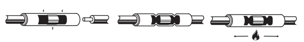
- Strip both wires 3/8”Insert wire into barrel
- Crimp colored dots on barrel. If no dots present, crimp on the center of barrel between end of solder sleeve and end of crimp barrel.
- Heat tubing
- When the window appears and most of the red dye disappears, the solder has flowed into the crimp barrel. Remove from heat.
For best results: Use heat device of at least 1000°F. Don’t overheat tubing. Don’t isolate flame. Distribute heat evenly over tubing. Heat until solder flows into wires and window in the center of connector appears. Some red dye may remain in the window &/or “pool” opposite of the window. Crimp middle of barrel between the solder and the barrel’s end. If you crimp off-center, on either end of the barrel, discard the connector and start over.
Unless otherwise stated: Max. Temp 221°F, 600V Max. building wire, 1000V Max. signs & fixtures, stranded copper conductors only.